-30%
Jamaican Black Castor Oil


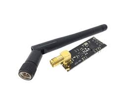
DescriptionThis wireless Transceiver module is an easy and suitable module if you want to setup your wireless communication system with low cost. It can achieve a good balance between wireless transition performance and cost. You can easily add it with your own MCU/ARM/PIC/AVR/STM32 system. What’s more, this nRF24L01 module is designed with Power amplifier and SMA antenna. This allows you to use the wireless communication up to 1000 meters! (No barrier)Specifications:Frequence: 2.4GHz~2.5GHzOperating voltage: 3 ~ 3.6V MaxCurrent: 115mAMulti-frequency: 125 frequencySupport up to six channels of data receptionGetting started with the 2.4G NRF24L01 PA LNA SMA Antenna Wireless Transceiver communication moduleIn our experiment we will just send a traditional ‘Hello World’ message from the transmitter to the receiver.Step1: Hardware requiredArduino UNO2pcs × NRF24L01 with Antenna (One for Transmitter and another for Receiver)Jumper wiresStep2: Connecting the HardwareTo start with, connect VCC pin on the module to 3.3V on the Arduino and GND pin to ground. The pins CSN and CE can be connected to any digital pin on the Arduino. In our case, it’s connected to digital pin#8 and #9 respectively. Now we are remaining with the pins that are used for SPI communication.As nRF24L01 transceiver module require a lot of data transfer, they will give the best performance when connected up to the hardware SPI pins on a microcontroller. The hardware SPI pins are much faster than ‘bit-banging’ the interface code using another set of pins.Note that each Arduino Board has different SPI pins which should be connected accordingly. For Arduino boards such as the UNO/Nano V3.0 those pins are digital 13 (SCK), 12 (MISO) and 11 (MOSI).If you have a Mega, the pins are different! You’ll want to use digital 50 (MISO), 51 (MOSI), 52 (SCK), and 53 (SS). Refer below table for quick understanding.MOSIMISOSCKArduino UNO111213Arduino Nano111213Arduino Mega515052Remember! You need to make two of these circuits. One acts as a transmitter and the other as a receiver. The wiring for both is identical.Step3: Setting up the libraryBefore making the sketch make sure you have the NRF24 library if not, you can download it hereAfter download the library extract it to the arduino library folder as shown belowOr if you have the 1.6.0 and above version of the arduino IDE you can simply download and install library as shown below, by opening the sketch tab>include libary>manage libraryAfter opening manage library wait a bit to search for libraries, after go to search tab type in “RF24” and install the library as shown belowAfter installing the library you need to check in the include library if it is there so go to sketch>include library you will see the RF24 lite.As shown, the library is well installed correctly.Step4: Upload the sample sketchArduino CODE for TransmitterIn our experiment we will just send a traditional ‘Hello World’ message from the transmitter to the receiver.Here is the sketch we will be using for our transmitter://Include Libraries #include <SPI.h> #include <nRF24L01.h> #include <RF24.h> //create an RF24 object RF24 radio(9, 8); // CE, CSN //address through which two modules communicate. const byte address[6] = "00001"; void setup() { radio.begin(); //set the address radio.openWritingPipe(address); //Set module as transmitter radio.stopListening(); } void loop() { //Send message to receiver const char text[] = "Hello World"; radio.write(&text, sizeof(text)); delay(1000); }Arduino CODE for ReceiverHere is the sketch we will be using for our receiver//Include Libraries #include <SPI.h> #include <nRF24L01.h> #include <RF24.h> //create an RF24 object RF24 radio(9, 8); // CE, CSN //address through which two modules communicate. const byte address[6] = "00001"; void setup() { while (!Serial); Serial.begin(9600); radio.begin(); //set the address radio.openReadingPipe(0, address); //Set module as receiver radio.startListening(); } void loop() { //Read the data if available in buffer if (radio.available()) { char text[32] = {0}; radio.read(&text, sizeof(text)); Serial.println(text); } }Step5: Testing the circuitAt the end we just print the received message on serial monitor. If you did everything ok and there are no mistakes in connections, you should see something like this in your Serial Monitor. Package includes: 1×nRF24L01 Wireless Module