-30%
Jamaican Black Castor Oil


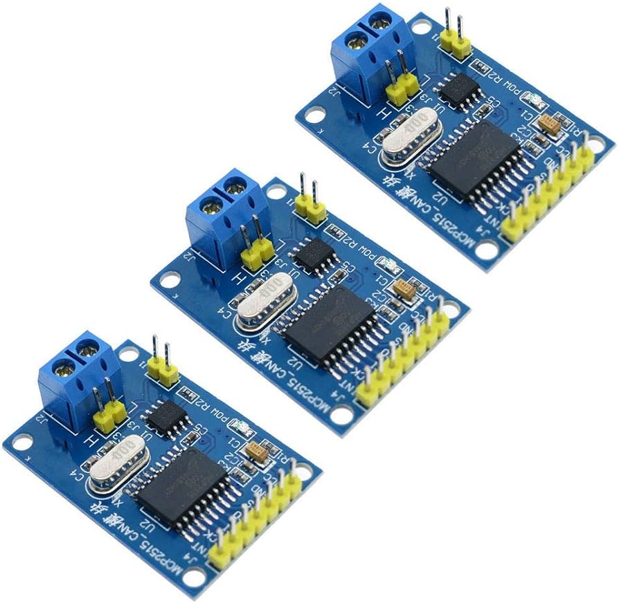
DescriptionThe MCP2515 CAN Bus Controller is a simple Module that supports CAN Protocol version 2.0B and can be used for communication at 1Mbps. In order to setup a complete communication system.This particular module is based on MCP2515 CAN Controller IC and TJA1050 CAN Transceiver IC. The MCP2515 IC is a standalone CAN Controller and has integrated SPI Interface for communication with microcontrollers.Coming to the TJA1050 IC, it acts as an interface between the MCP2515 CAN Controller IC and the Physical CAN Bus.Pin DefinitionsVCC 5V power input pinGND power ground pinCS SPI SLAVE select pin (Active Pin)SO SPI master output slave input pinSCLK SPI clock pinINT MCP2515 interrupt pinProduct Description1, support CAN V2.0B specification, the communication speed 1Mb / S2,0 to 8-byte data field3, the standard frame and expand the frame and remote frame4. 5V DC power supply module, SPI interface protocol control5,120 ohm termination resistors. Impedance matching, ensure drive capacity, long-distance data transmission against signal radiation6, module size: 4.4cm x 2.8cm screw hole center spacing 23mm x 38mm7, the working current: typ. 5mA, 1 microamp standby current. Except the power indicator.8, the working temperature: Industrial grade to 85 ℃ -40 ℃Getting started with the MCP2515 Controller Bus Module TJA1050 Receiver SPI Protocol for ArduinoIn this project, we will learn about the MCP2515 CAN Controller Module, how to interface the MCP2515 CAN Bus Controller with Arduino and finally how to enable communication between two Arduino board with the help of two MCP2515 CAN Controllers and the CAN Protocol.Hardware requiredArduino UNO MCP2515 Connecting WiresConnecting the HardwareThe following image shows the circuit diagram of interfacing MCP2515 CAN Module with Arduino and possible communication between two Arduino over CAN Protocol.CodeBefore going into the code, you need to download a library for the MCP2515 Module. There are many libraries but I have used this particular one.Download it and place the extracted contents in the libraries directory of Arduino.Since the communication involves a Transmitter Module and a Receiver Module, the code is also divided into Transmitter Code and Receiver Code.Transmitter Code#include <SPI.h> #include <mcp_can.h>const int spiCSPin = 10; int ledHIGH = 1; int ledLOW = 0;MCP_CAN CAN(spiCSPin);void setup() { Serial.begin(115200);while (CAN_OK != CAN.begin(CAN_500KBPS)) { Serial.println(“CAN BUS init Failed”); delay(100); } Serial.println(“CAN BUS Shield Init OK!”); }unsigned char stmp[8] = {ledHIGH, 1, 2, 3, ledLOW, 5, 6, 7};void loop() { Serial.println(“In loop”); CAN.sendMsgBuf(0x43, 0, 8, stmp); delay(1000); }Receiver Code#include <SPI.h> #include “mcp_can.h”const int spiCSPin = 10; const int ledPin = 2; boolean ledON = 1;MCP_CAN CAN(spiCSPin);void setup() { Serial.begin(115200); pinMode(ledPin,OUTPUT);while (CAN_OK != CAN.begin(CAN_500KBPS)) { Serial.println(“CAN BUS Init Failed”); delay(100); } Serial.println(“CAN BUS Init OK!”); }void loop() { unsigned char len = 0; unsigned char buf[8];if(CAN_MSGAVAIL == CAN.checkReceive()) { CAN.readMsgBuf(&len, buf);unsigned long canId = CAN.getCanId();Serial.println(“—————————–“); Serial.print(“Data from ID: 0x”); Serial.println(canId, HEX);for(int i = 0; i<len; i ) { Serial.print(buf[i]); Serial.print(“\t”); if(ledON && i==0) {digitalWrite(ledPin, buf[i]); ledON = 0; delay(500); } else if((!(ledON)) && i==4) {digitalWrite(ledPin, buf[i]); ledON = 1; } } Serial.println(); } }WorkingWorking of this project is very simple as all the work is done by the libraries (SPI and CAN). Since CAN is message-based communication, you need to send a message anywhere between 0 and 8 bytes.In this project, the transmitter is sending a message as 1 1 2 3 0 5 6 7. This message is transmitted over CAN Bus and the receiver receives this message and is displayed on its serial monitor.Additionally, the 0th and 4th bit i.e. 1 and 0 in the above sequence are extracted separately by the receiver and turns ON and OFF the LED connected to Pin 2 of Arduino.