-30%
Jamaican Black Castor Oil


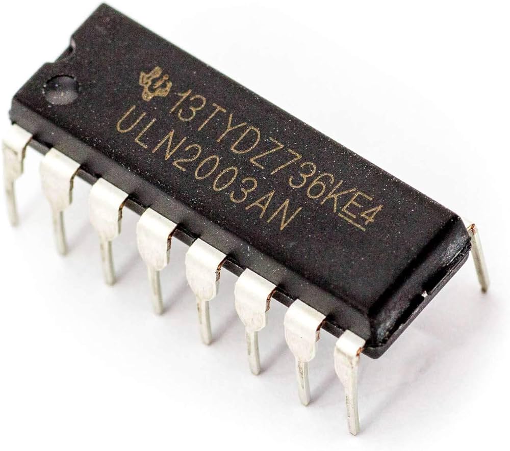
DescriptionPin ConfigurationPin NumberPin NameDescription1 to 7Input 1 to Input 7Seven Input pins of Darlington pair, each pin is connected to the base of the transistor and can be triggered by using 5V8GroundGround Reference Voltage 0V9COMUsed as test pin or Voltage suppresser pin (optional to use)10 to 16Output 1 to Output 7Respective outputs of seven input pins. Each output pin will be connected to ground only when its respective input pin is high( 5V) FeaturesContains 7 high-voltage and high current Darlington pairsEach pair is rated for 50V and 500mAInput pins can be triggered by 5VAll seven Output pins can be connected to gather to drive loads up to (7×500mA) ~3.5A.Can be directly controlled by logic devices like Digital Gates, Arduino, PIC etcAvailable in 16-pin DIP, TSSOP, SOIC packagesWhere to use a ULN2003ULN2003 IC is one of the most commonly used Motor driver IC. This IC comes in handy when we need to drive high current loads using digital logic circuits like Op-maps, Timers, Gates, Arduino, PIC, ARM etc. For example a motor that requires 9V and 300mA to run cannot be powered by an Arduino I/O hence we use this IC to source enough current and voltage for the load. This IC is commonly used to drive Relay modules, Motors, high current LEDs and even Stepper Motors. So if you have anything that anything more than 5V 80mA to work, then this IC would be the right choice for you.How to use a ULN2003The ULN2003 is a 16-pin IC. It has seven Darlington Pairs inside, where each can drive loads up to 50V and 500mA. For these seven Darlington Pairs we have seven Input and Output Pins. Adding to that we can a ground and Common pin. The ground pin, as usual is grounded and the usage of Common pin is optional. It might be surprising to note that this IC does not have any Vcc (power) pin; this is because the power required for the transistors to work will be drawn from the input pin itself. The below circuit is a simple circuit that can be used to test the working of ULN2003 ICIn the circuit consider the LED to be the loads and the logic pins (blue colour) as the pins connected to the Digital circuit or Microcontroller like Arduino. Notice that the Positive pin of the LED is connected to the positive load voltage and the negative pin is connected to the output pin of the IC. This is because when the input pin of the IC gets high the respective output pin will get connected to ground. So when the negative terminal of the LED is grounded it completes the circuit and thus glows. The loads connected to the output pin can be maximum of 50C and 500mA each. However you can run higher current loads buy combining two or more output pins to gather. For example if you combine three pins you can drive up to (3*500mA) ~1.5A.The COM pin is connected to ground through a switch, this connection is optional. It can be used a test switch, meaning when this pin is grounded all the output pins will be grounded.ApplicationsUsed to drive high current loads using Digital CircuitsCan be used to drive Stepper motorsHigh current LED’s can be drivenRelay Driver module (can drive 7 relays)Logic Buffers in digital electronicsUsed as Touch sensor for ArduinoDocument:Datasheet