-30%
Jamaican Black Castor Oil


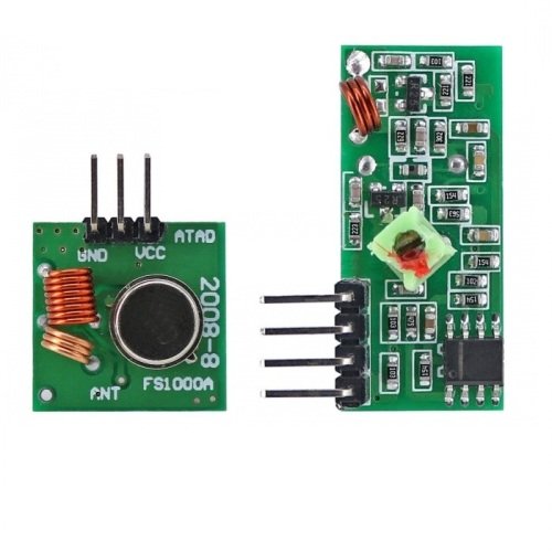
DescriptionThese 433MHz RF module is consisted of transmitter and receiver, popularly used for remote control. are very popular among the Arduino tinkerers. The 433MHz is used on a wide variety of applications that require wireless control.Specifications RF 433MHz ReceiverVoltage:DC5VCurrent:4MAFrequency:433.92MHZSensitivity:-105DBAntenna:32CM single core wire,heliciform shaped Specifications RF 433MHz TransmitterTransmitter distance:20-200Meters(influenced the voltage)Voltage:3.5-12VTransmitter speed:4KB/STransmitter power:10mWFrequency:433MAttenna:25cm Single core wire or mutil-core wirePin arrangement: left-right(DATA;VCC;GND)Applications: Remote controller, receive module, car bugular alarm, Rolling door, window, remote control LED, Amplifer .Note: VCC Voltage should be comply with working voltageAntenna is very important for working voltage, and the length of the antenna is 17cmThe placement of the antenna is also critical for the performance of receiver,Unbend the antenna when you install it, and avoid shilder and high voltageGetting started with the RF wireless receiver module & transmitter module board for arduino 433Mhz DC5VIn this section, we’ll build a simple example that sends a message from an Arduino to another Arduino board using 433 MHz. An Arduino board will be connected to a 433 MHz transmitter and will send the “Hello World!” message. The other Arduino board will be connected to a 433 MHz receiver to receive the messages.Step1: Hardware requiredArduino UNOBreadboardJumper wires433MHz RF Transmitter and ReceiverStep2: Connecting the HardwareThe wiring for the transmitter is fairly simple. It has only three connections. Connect the VCC pin to 5V pin and GND to ground on the Arduino. The Data-In pin should be connected to Arduino’s digital pin #12. You should try and use pin 12 as by default the library we’ll be using in our sketch uses this pin for data input.Once you have the transmitter wired you can move on to the receiver. The wiring for the receiver is just as easy as the transmitter was.Once again there are only three connections to make. Connect the VCC pin to 5V pin and GND to ground on the Arduino. Any of the middle two Data-Out pins should be connected to digital pin #11 on the Arduino.Now that both the transmitter and receiver are wired up we will need to write some code and send it to the respective Arduino boards. Since you probably have only one PC, we will start with the transmitter. Once the code has been loaded there, we’ll move on to the receiver. The Arduino to which transmitter is connected can then be powered using a power supply or battery.Step3: Setting up the libraryBefore we start coding, there is a library called RadioHead we will need to install into our Arduino IDE that will make writing the code a lot simpler.RadioHead is a library that allows simple data transfer between Arduino boards. It’s so versatile that it can be used to drive all sorts of radio communications devices, including our 433MHz modules.You can download the library, just click this RadioHead.Zip to download the zip: RadioHead.ZipTo install it, open the Arduino IDE, go to Sketch > Include Library > Add .ZIP Library, and then select the RadioHead file that you just downloaded.Step4: Upload the sample sketchIn our experiment we will just send a simple text message from the transmitter to the receiver. It will be helpful to understand how to use the modules and can serve as the basis for more practical experiments and projects.Here is the sketch we will be using for our transmitter:#include <RH_ASK.h> #include <SPI.h> // Not actually used but needed to compile RH_ASK driver; // RH_ASK driver(2000, 2, 4, 5); // ESP8266 or ESP32: do not use pin 11 void setup() { Serial.begin(9600); // Debugging only if (!driver.init()) Serial.println("init failed"); } void loop() { const char *msg = "hello"; driver.send((uint8_t *)msg, strlen(msg)); driver.waitPacketSent(); delay(200); }Connect the receiver Arduino to the computer and load the following code:#include <RH_ASK.h> #include <SPI.h> // Not actualy used but needed to compile RH_ASK driver; // RH_ASK driver(2000, 2, 4, 5); // ESP8266 or ESP32: do not use pin 11 void setup() { Serial.begin(9600); // Debugging only if (!driver.init()) Serial.println("init failed"); } void loop() { uint8_t buf[5]; uint8_t buflen = sizeof(buf); if (driver.recv(buf, &buflen)) // Non-blocking { int i; // Message with a good checksum received, dump it. //driver.printBuffer("Got:", buf, buflen); String msg="Message: "; Serial.println(msg (char*)buf); } }Step5: Testing the circuitAfter loading the sketch open your serial monitor. If all is OK you should see your message.