-30%
Jamaican Black Castor Oil


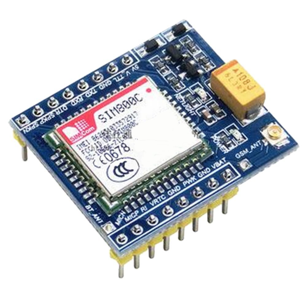
DescriptionThis GSM/GPRS developemnt board is based on SIM800C chip supporting bluetooth function and AT command control via the serial prot. On-board SIM card slot and support 850/900/1800/1900MHz quad band can be used worldwide. It is equipped with 5V/3.3V ligic converter circuit compatible with most MCU breakout board to obtain the SMS and TTS function.Chip: SIM800C Band: 850/900/1800/1900MHz GPRS multi-slot class: 12/10 GPRS mobile station class: B Compliant to GSM phase 2/2 – Class 4 (2 W @ 850/900 MHz) – Class 1 (1 W @ 1800/1900MHz) Control via AT commands (3GPP TS 27.007, 27.005 and SIMCOM enhanced AT Commands) Board Size: 30.73 X 26.56mm/1.21 X 1.05inch(L*W)FeaturesPower input: DC5V or received by a lithium battery input VBAT and GND.Supports MCU level: 5V / 3.3V for TTL logic (Such as the common 51 and the arduino is 5v, STM32 is the 3.3v)Antenna use: IPEX antenna interfaces, you can use the version PCB antenna or antenna IPEX-SMA- peppersGetting started with the SIM800C GSM GPRS Module with Bluetooth and TTS for ArduinoThis GSM/GPRS developemnt board is based on SIM800C chip supporting bluetooth function and AT command control via the serial pot. On-board SIM card slot and support 850/900/1800/1900MHz quad band can be used worldwide.Pin Description5V: power supply pin, the only input DC5V, used to power the board.V_TTL: access control board microcontroller core target voltage of 5V / 3.3V (according to its own microcontroller is much to distinguish – kernel v), this pin is used to convert the GSM module board TXD and RXD for the corresponding TTL logic.GND: power supply groundTXD: send pin serial port module, TTL level (not directly connected to RS232 level)RXD: receive pin serial port module, TTL level (not directly connected to RS232 level)DTR: Data Terminal ReadySPKP: Core Audio output pinSPKN: Core Audio output pinMICN: Core Audio inputMICP: Core Audio inputRI: Ring core pin tipsVRTC: RTC pin external batteryGND: power supply groundPWX: This pin can turn down or turn off the moduleGND: power supply groundVBAT: lithium battery input pin, 3.3v-4.4vHardware requiredArduino unoGSM SIM800 with bluetoothBreadboardJumper wiresLithium battery 3.7vConnecting the HardwareGSM SIM800C Arduino UnoVBAT of batteryGND – of batteryPWX GNDTx D3Rx D2Arduino Code – Testing AT CommandsFor sending AT commands and communicating with the SIM800C module, we will use the serial monitor. The sketch below will enable the Arduino to communicate with the SIM800C module on serial monitor. Before we proceed with detailed breakdown of code, connect your Arduino to PC, compile below code and upload it to the Arduino.Once you open a serial monitor, make sure that ‘Both NL & CR’ option is selected!#include <SoftwareSerial.h> //Create software serial object to communicate with SIM800C SoftwareSerial mySerial(3, 2); //SIM800C Tx & Rx is connected to Arduino #3 & #2 void setup(){ //Begin serial communication with Arduino and Arduino IDE (Serial Monitor) Serial.begin(9600); //Begin serial communication with Arduino and SIM800C mySerial.begin(9600); Serial.println("Initializing..."); delay(1000); mySerial.println("AT"); //Once the handshake test is successful, it will back to OK updateSerial(); mySerial.println("AT CSQ"); //Signal quality test, value range is 0-31 , 31 is the best updateSerial(); mySerial.println("AT CCID"); //Read SIM information to confirm whether the SIM is plugged updateSerial(); mySerial.println("AT CREG?"); //Check whether it has registered in the network updateSerial(); } void loop(){ updateSerial(); } void updateSerial(){ delay(500); while (Serial.available()){ mySerial.write(Serial.read());//Forward what Serial received to Software Serial Port } while(mySerial.available()){ Serial.write(mySerial.read());//Forward what Software Serial received to Serial Port } }Now that we have established a basic connection, we will try to communicate with the SIM800L module by sending AT commands.AT – It is the most basic AT command. It also initializes Auto-baud’er. If it works you should see the AT characters echo and then OK, telling you it’s OK and it’s understanding you correctly! You can then send some commands to query the module and get information about it such asAT CSQ – Check the ‘signal strength’ – the first # is dB strength, it should be higher than around 5. Higher is better. Of course it depends on your antenna and location!AT CCID – get the SIM card number – this tests that the SIM card is found OK and you can verify the number is written on the card.AT CREG? Check that you’re registered on the network. The second # should be 1 or 5. 1 indicates you are registered to home network and 5 indicates roaming network. Other than these two numbers indicate you are not registered to any network.You should see below output on serial monitor. You are now free to send any commands through serial monitor like below which gives more information about network connection & battery status:ATI – Get the module name and revisionAT COPS? – Check that you’re connected to the network, in this case BSNLAT COPS=? – Return the list of operators present in the network.Arduino Code – Sending SMSLet’s move on to the interesting stuff. Let’s program our Arduino to send an SMS to any phone number you wish. Before trying the sketch out, you need to enter the phone number. Search for the string ZZxxxxxxxxxx and replace ZZ with county code and xxxxxxxxxx with the 10 digit phone number.#include <SoftwareSerial.h> //Create software serial object to communicate with SIM800L SoftwareSerial mySerial(3, 2); //SIM800C Tx & Rx is connected to Arduino #3 & #2 void setup(){ //Begin serial communication with Arduino and Arduino IDE (Serial Monitor) Serial.begin(9600); //Begin serial communication with Arduino and SIM800C mySerial.begin(9600); Serial.println("Initializing..."); delay(1000); mySerial.println("AT"); //Once the handshake test is successful, it will back to OK updateSerial(); mySerial.println("AT CMGF=1"); // Configuring TEXT mode updateSerial(); mySerial.println("AT CMGS=\" ZZxxxxxxxxxx\"");//change ZZ with country code and xxxxxxxxxxx with phone number to sms updateSerial(); mySerial.print("Faranux Electronics | faranux.com"); //text content updateSerial(); mySerial.write(26); } void loop(){} void updateSerial(){ delay(500); while (Serial.available()){ mySerial.write(Serial.read());//Forward what Serial received to Software Serial Port } while(mySerial.available()){ Serial.write(mySerial.read());//Forward what Software Serial received to Serial Port } }The sketch is almost same as earlier except below code snippet. Once the connection is established, we send below AT commands:AT CMGF=1 – Selects SMS message format as text. Default format is Protocol Data Unit (PDU)AT CMGS= ZZxxxxxxxxxx – Sends SMS to the phone number specified. The text message entered followed by a ‘Ctrl z’ character is treated as SMS. ‘Ctrl z’ is actually a 26th non-printing character described as ‘substitute’ in ASCII table. So, we need to send 26DEC (1AHEX) once we send a message.Arduino Code – Reading SMSNow let’s program our Arduino to read incoming messages. This sketch is very useful when you need to trigger an action when a specific SMS is received. For example, when the Arduino receives an SMS, you can instruct it to turn on or off a relay. You got the idea!#include <SoftwareSerial.h> //Create software serial object to communicate with SIM800C SoftwareSerial mySerial(3, 2); //SIM800C Tx & Rx is connected to Arduino #3 & #2 void setup(){ //Begin serial communication with Arduino and Arduino IDE (Serial Monitor) Serial.begin(9600); //Begin serial communication with Arduino and SIM800C mySerial.begin(9600); Serial.println("Initializing..."); delay(1000); mySerial.println("AT"); //Once the handshake test is successful, it will back to OK updateSerial(); mySerial.println("AT CMGF=1"); // Configuring TEXT mode updateSerial(); mySerial.println("AT CNMI=1,2,0,0,0"); // Decides how newly arrived SMS messages should be handled updateSerial(); } void loop(){ updateSerial(); } void updateSerial(){ delay(500); while (Serial.available()){ mySerial.write(Serial.read());//Forward what Serial received to Software Serial Port } while(mySerial.available()){ Serial.write(mySerial.read());//Forward what Software Serial received to Serial Port } }Once you send the SMS to SIM800L GSM module, you will see below output on serial monitor.Package includes: 1×SIM800C Module